
On-site solar photovoltaic (PV) systems can be made more resilient to severe weather events by leveraging lessons learned from field examinations of weather-damaged PV systems and from engineering guidance resources.
Reducing Storm Damage and Increasing Resilience
According to a National Laboratory of the Rockies (NLR) report, Solar Photovoltaics in Severe Weather: Cost Considerations for Storm Hardening PV Systems for Resilience, some measures to improve durability will result in higher upfront costs. However, these costs need to be weighed against the benefits of a more robust system with lower outyear costs for maintenance, administrative burdens, repair, and downtime/loss of production.
Solar PV Is a Reliable Source of Generation
PV technologies are highly reliable. Analysis of performance data from 100,000 PV systems concluded that over 80% of systems performed within 10% of predicted production.
The estimated initial costs of 13 storm hardening measures are listed in Table 1.
Table 1. Storm Hardening Measures for PV Systems and Their Added Cost
Measure Base Case Hardened Case Ground Mount Premium Roof Mount Premium 1. System Audit No system audit Perform a system audit 0.05 ¢/W (2%1)
2.5 ¢/W (100%2)
0.05 ¢/W (2%)
2.7 ¢/W (100%)
2. Locking Fasteners Hex bolts, flange nuts, stainless steel flat washers Several different options explored 0.1-1.4 ¢/W 0.1-1.5 ¢/W 3. Through Bolting Top-down clamps Through bolts 0.6 ¢/W 0.7 ¢/W 4. Marine-Grade Steel 18-8 stainless steel 316 stainless steel 1.1 ¢/W 1.2 ¢/W 5. Module Selection Standard modules (2400 Pa uplift) Highest rated modules (≥ 3600 Pa uplift) 10 ¢/W 10 ¢/W 6. Three-Framed Rail System Two-rail racking Three-rail racking 5.2 ¢/W 5.7 ¢/W 7. Two-Pier Mounting One driven steel pier Dual post piers 5.9 ¢/W N/A 8. Racking Design Cold rolled U channel aluminum Tubular aluminum 12 ¢/W N/A 9. Wind-Calming Fence Standard security fence Wind calming fence around perimeter 6-14 ¢/W N/A 10. Watertight Enclosures National Electrical Manufacturers Association (NEMA) 3 rated NEMA 4X rated Recommendation only 11. Elevated Pads Electronic components not on elevated pads Electronic components installed on elevated concrete pads 0.8-1.0 ¢/W N/A 12. Drainage Not well-designed drainage systems Well designed and maintained drainage Recommendation only. Should be a standard design component. 13. Pre- and Post-Storm Measures None taken Powering down, cleaning site, fault testing, repair/replace Recommendation only. Costs are too variable based on site and which measures are undertaken. 1 If 2% of the fasteners in a system are torque checked.
2 If 100% of the fasteners in a system are torque checked.
Step 1. Assess the Site for Weather Events
Severe weather events strong enough to cause damage to a solar PV system occur in nearly every region of the country. The Federal Emergency Management Agency (FEMA) produces a National Risk Index (NRI) which details 18 weather and environmental parameters at a county level. Use the NRI tool to look up weather risks at your site. If the results show at least "relatively high" rating for a weather event, then the technical specifications shown below should be added to solicitation and contract documents (see Step 2).
Step 2. Include Technical Specifications Related to Each Weather Risk
Apply the Recommended Actions by adding specifications to the solicitation and contract documents. Easy-to-copy specification language is provided in callout boxes.
Wind Technical Requirements
The Federal Energy Management Program (FEMP) provides the following recommendations to inform the technical requirements of a solicitation and contract.
Recommended Actions for Incorporating Wind Guidance
Use these design and engineering guidance documents when the FEMA NRI indicates at least a "relatively high" risk of "Strong Winds" at a given site. Confirm that the guidance is utilized by project engineers during the design review process.
American Society of Civil Engineers/Structural Engineering Institute (ASCE/SEI) 7-22 Minimum Design Loads and Associated Criteria for Buildings and Other Structures
Structural Engineers Association of California (SEAOC) Solar Photovoltaic Systems Committee PV2-2017 Wind Design for Solar Arrays
Rocky Mountain Institute (RMI) and Clinton Climate Initiative (CCI) Solar Under Storm Part I and II
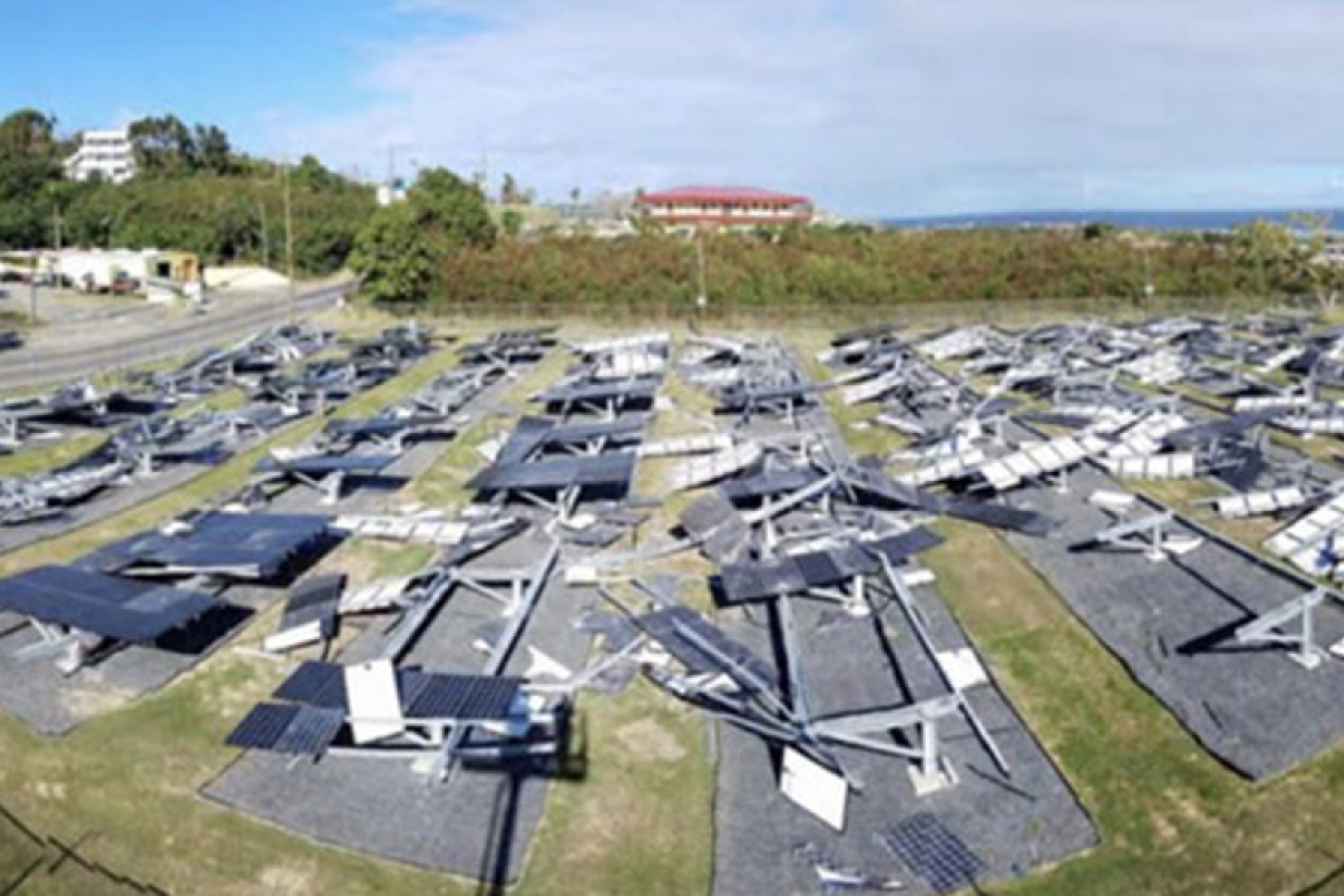
When exposed to wind, all objects vibrate, and depending on several characteristics of the array structures, arrays may experience violent resonance or severe frame member deflection, which could lead to catastrophic losses. Ensure that the racking design is engineered to withstand highly turbulent wind forces.
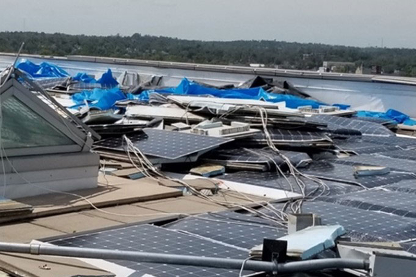
Due to the turbulence generated by wind flowing over parapets and around roof penthouses, solar PV roof systems should not be fully ballasted. Use mechanical attachments at strategic locations to prevent catastrophic loss.
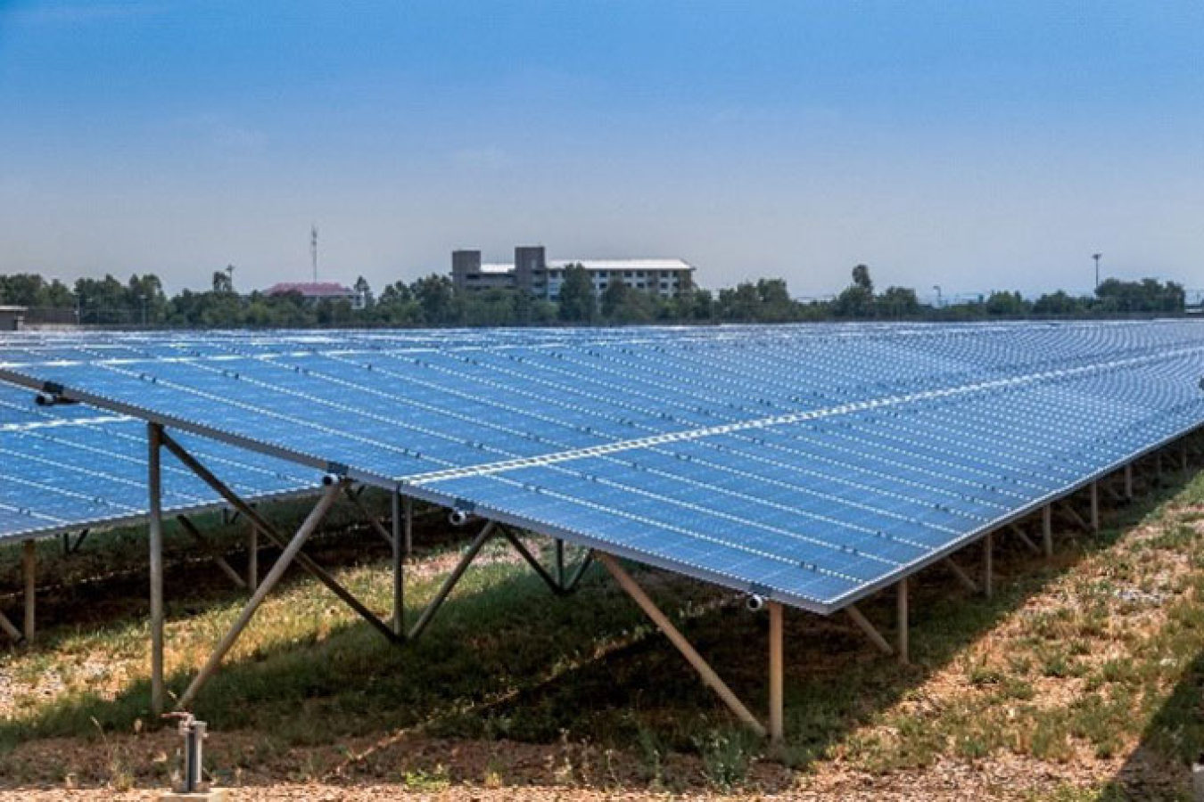 PV array with a braced design.
Racking designs with vertical frame members need bracing to prevent lateral movement.
Recommended Actions for Lateral Bracing
Require that racking designs anticipate lateral movement and are properly braced. One simple indicator of a racking system's ability to resist lateral movement is the presence of cross-bracing in design drawings.
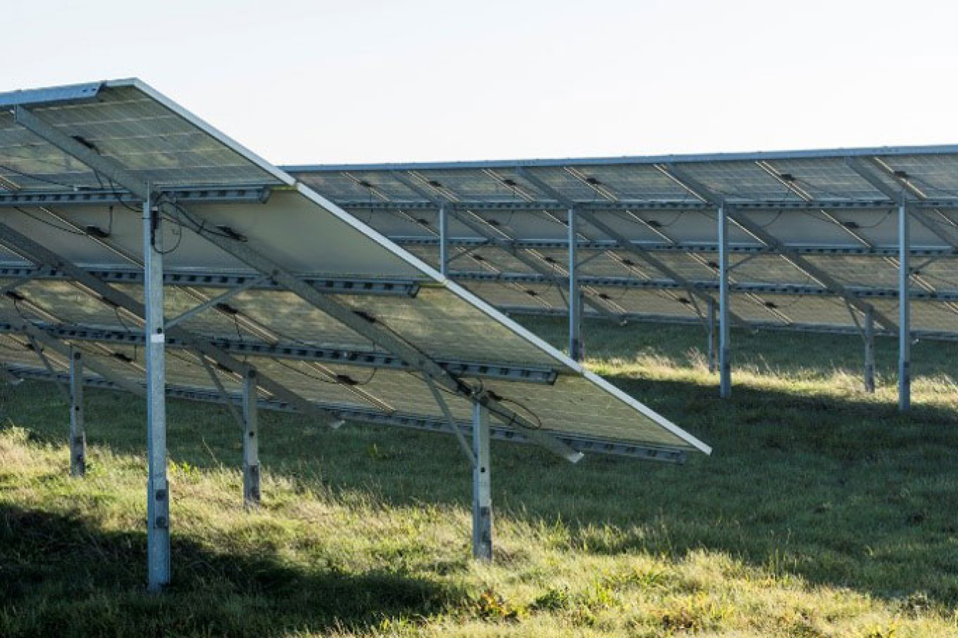 PV array with no lateral bracing.
Suggested Specification Language for Racking Systems
Racking system specified shall be designed to withstand lateral forces from all wind approach angles.
 Structural channel deformed from extreme flexing.Photo from Gerald Robinson, LBNL
Rack frame elements comprised of light gauge structural channels have been shown to lack torsional strength and tend to flex in wind events. Torsional movement and significant flexing create a load path to the mounted modules and fasteners. This can damage the fasteners holding the modules in place or even fracture the modules in extreme cases.
Suggested Technical Requirements
A proposed design shall incorporate design features that can accommodate dynamic wind loading from any direction and prevent torsional movement and/or significant flexing.
Fastened joints are bolts, clips, and brackets designed to hold two or more parts together. Fastened joints are found throughout a solar PV system to mount solar modules to racking systems, hold racking frame elements together, and provide a means of mechanical attachment to foundations (for ground and carport arrays) or to a building structure (for roof arrays). Critical fastened joints are defined as the assembly of fastened components whose failure will result in a catastrophic outcome. For example, if fastened joints used to mount the module to the racking framework fail, modules could become dangerous airborne debris. Module mounting and racking assemblies typically have many critical fastened joints.
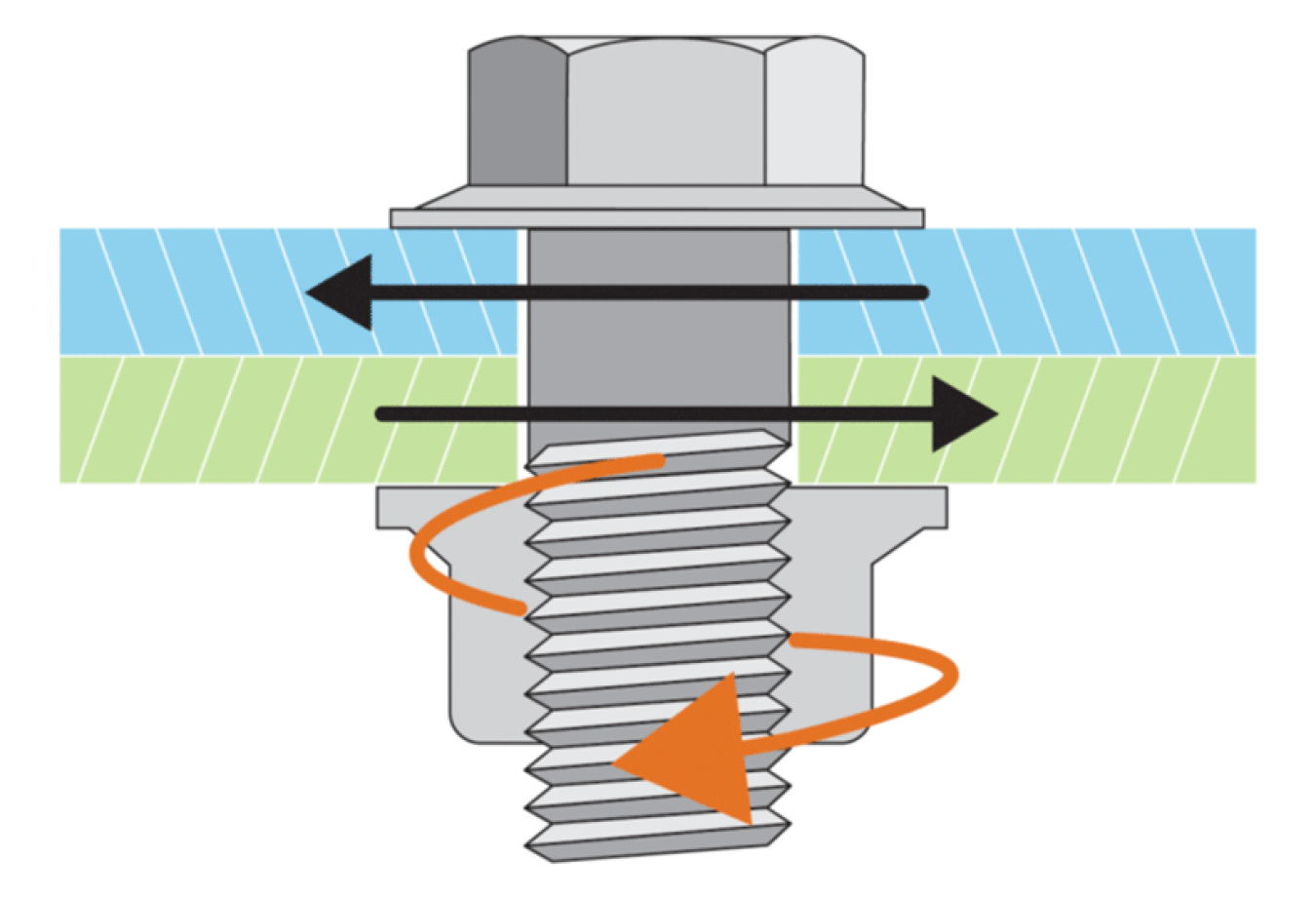 Slip in a fastened joint causing loosening.Illustration from NLR, based on an image from Matrix Engineering.
Many failures observed in the field have been the result of issues with fastened joints and components. There are broad common categories of failures seen with fastened joints:
- Procurement of sub-standard components
- Poor installation practices; not using torque wrenches and thread lubricant
- Inadequate strength for the actual loading
- Vibration-induced loosening of threaded fasteners
- Joint relaxation – loosening of fasteners after initial installation
- Module mid-clamps fail, releasing an entire row of modules causing cascading failures.
Recommended Actions for Critical Fastened Joints
To reduce likelihood of fastened joint failures, use the following design guidelines:
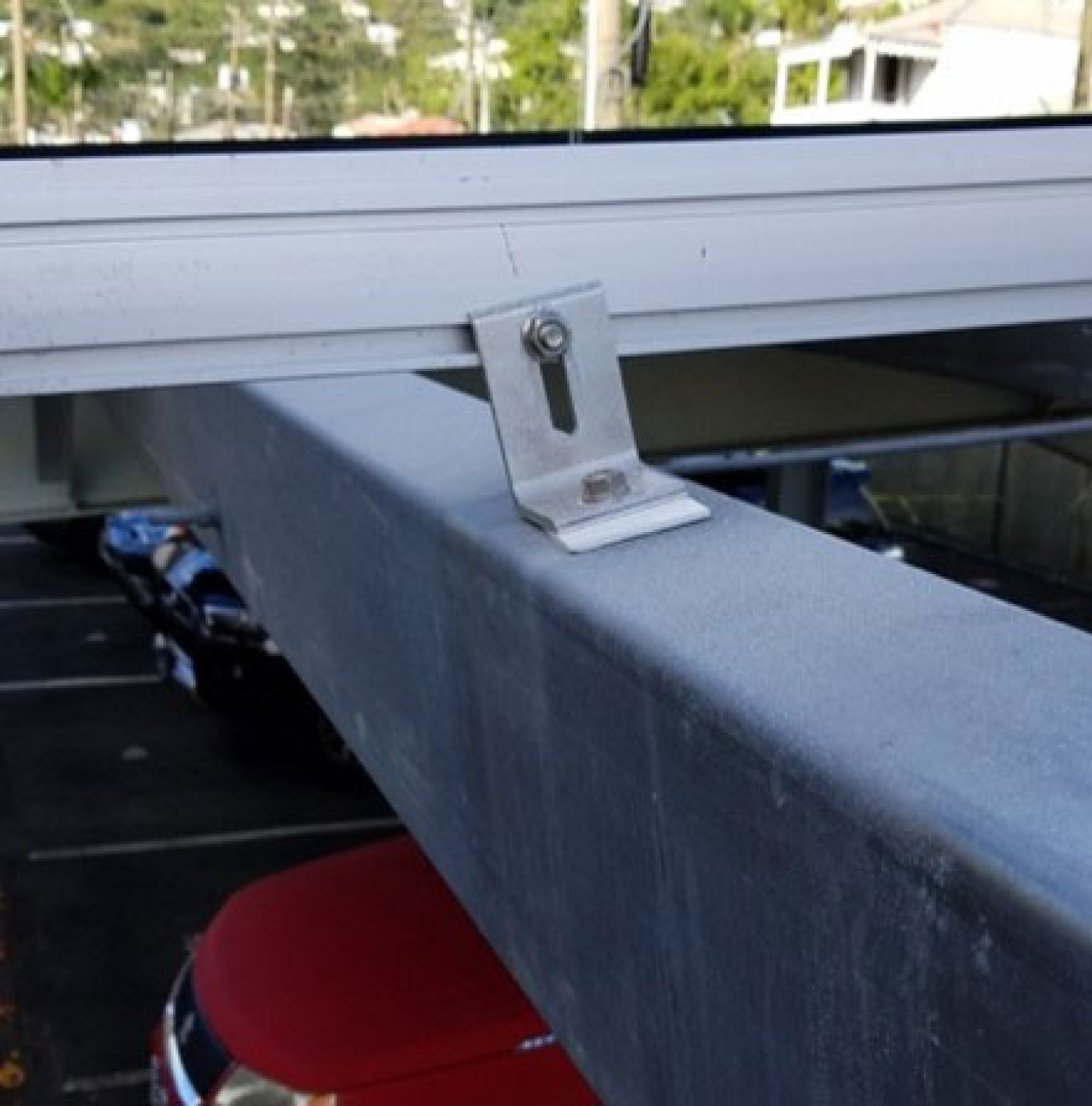
- Through-bolt modules to the racking system to avoid use of top-down clamping systems when possible. Add hardware to compensate for short fastener lengths.
- Never assemble critical structural fastened joints with self-tapping sheet metal screws or clamps.
- Threaded fasteners should include locking mechanisms rated to DIN 25201 part B standards (DIN 25201-4) to address vibrational loosening and resulting joint slip. Avoid using unrated hardware such as split washers, nylon insert nuts, double-nutting, star washers, and/or serrated flange nuts. Thread locking compounds, while effective, have unknown longevity when exposed to exterior elements and should be avoided as a sole locking means of a fastened joint. Movement or slip in a joint is the main force that induces loosening of fastened joints. Many fastened joints in a solar PV system are subjected to transverse slip, so it is recommended that vibration resistant fasteners be specified and installed on all critical fastened joints in a solar array.
Suggested Specification Language for Fastened Joints
Contractor shall utilize racking designs that allow module frames to be directly fastened to the mounting rails through the factory predrilled frame holes. Utilize DIN 25201-rated locking fasteners to ensure that modules stay mounted under wind-induced vibration.
If top-down clamp systems are unavoidable, use only top-down clamps with large surface area that have been independently tested for strength rating sufficient to hold modules in place under extreme wind forces found at the project site.
Tracker manufacturers have developed controls strategies that drive rows of modules into a stow position if high wind is indicated. This stow position is typically near horizontal but with a slightly negative angle of attack with respect to the wind. This feature could be specified for tracking systems in areas with high wind risk.
Wind pressure can put substantial loads on the front and back of modules and lead to micro-cracking of the solar cells and even fracture of the module glass.
Recommended Actions for Front and Back Pressure Ratings
For modules placed in service at a site where the FEMA NRI tool shows relatively high risk of a strong wind event, specify modules with front and back pressure ratings. PV modules should be tested per ASTM E1830-15 prescribed test parameters for loading (snow and wind) of solar modules (front and back). This test also covers several other stress factors relevant to high winds such as the "twist test."
Minimum Front and Back Pressure Ratings for Loading Strength of Modules
Module Side Pascals Pounds per Square Foot Front Load (Push) Rating 5,400 113 Back Load (Pull) Rating 3,600 75 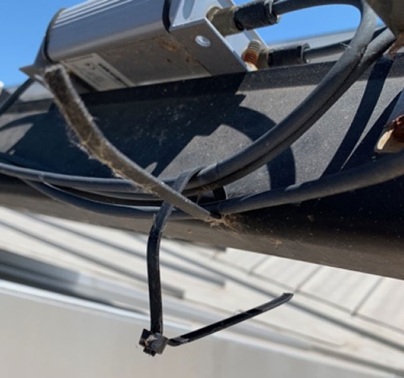 Loss of plastic wire ties.Photo from Gerald Robinson, LBNL
Poorly secured or routed wire can be damaged from weather events and cause electrical faults. Plastic wire ties (regardless of rating or material composition) can fail from exposure to heat, ultraviolet light, and moisture. There is general concern that even exterior-grade wire ties rated to be ultraviolet-resistant are inadequate for longevity in field use. If plastic ties fail, wind can cause the loose wire to rub against sharp edges or abrasive objects, resulting in electrical faults.
Suggested Technical Requirement for Wire Management
To prevent electrical faults, do not use plastic wire ties to secure string wiring. Instead, use purpose-built metal wire clips and ties and avoid versions that are plastic coated.
Most electrical switchgear is shipped with default cabinet options which are not suitable for areas with marine misting, high winds, or wind-driven rains. The default cabinets can collapse when exposed to heavy wind, driven rain can bypass door gasketing, and a standard door latch can blow open in high wind.
Requirements to Specify Suitable Grade of Electrical Enclosures
For sites where the FEMA NRI tool indicated "relatively high" risk of a strong wind event, electrical enclosures should have a minimum rating of NEMA 3, and if exposed to marine environments, should utilize NEMA 3RX. Sites in hurricane prone areas shall utilize NEMA 4X-rated enclosures. Fasteners should secure the perimeter of the door, not just the door handle, to keep the door closed.
Hail Technical Requirements
According to test lab engineers, most modules currently pass the IEC 61215 hail test standard, yet field experience has demonstrated that hail exceeding this standard can occur frequently in areas where FEMA indicates at least a "relatively high" risk of a hail event.
Learn more about how to determine and limit damage to PV systems.
Consider including one of these additional, extensive hail test standards to your solicitation and contract documents:
Suggested Specification Language for Hail Events
For sites at risk of moderate to severe hail, contractor shall select a module that meets either the FM Global "Very Severe Hail Rating" (FM 4478), or Renewable Energy Test Center Hail Durability Test, or the Photovoltaic Evolution Labs hail test standards.
Tracker manufacturers have developed controls strategies that drive rows of modules into a stow position if a hailstorm is predicted. This stow position is typically the maximum vertical tilt the tracker system allows, which should decrease the angle of impact of most hail balls. Some manufacturers have lab-tested these stow strategies using hail cannons and have demonstrated good results. Consider requiring the use of tracker technologies if the FEMA NRI resource indicates that hail is rated as a "relatively high" risk or greater for your site even though this may add cost.
Flooding Technical Requirements
Weather events that produce standing water and/or wind can flood underground pull boxes and conduit. Water can then flow into electrical cabinets that house inverters, switchgear, controls, meters, and transformers. Array fields that are either uphill from or at about the same elevation as supporting electrical equipment are at risk of unintentional flooding through pull boxes and conduit.
Suggested Technical Requirements to Prevent Flooding of Electrical Equipment
Require project engineers to place equipment at higher elevations than the array field and route conduit to prevent flooding. Cabinets shall be equipped with purpose-built one-way drain plugs to allow water to evacuate.
Step 3. Design Review Process
Include contract terms that require a design review and approval process to ensure that technical requirements have been incorporated into drawing sets. Design reviews and approvals typically occur at a few intervals, such as 25% (schematic), 75% (full draft), and 95% (pre-final).
Key Resources
Quick Links
Need Assistance?
Contact FEMP for assistance with on-site solar PV systems.