
Researchers at the Consortium for Computational Physics and Chemistry (CCPC) develop high-resolution, multi-scale, and multi-physics finite element models of catalytic upgrading reactors.
The catalytic upgrading reactor is downstream of the fast pyrolysis reactor in the ex situ catalytic fast pyrolysis biomass-to-fuel process. The catalyst in the reactor facilitates deoxygenation of the fast pyrolysis oil vapors through the reaction with hydrogen, which is introduced into the reactor.
Over time, carbon deposits build up on the catalyst as a byproduct of the deoxygenation reaction. These carbon deposits (known as “coke”) lead to reduced deoxygenation performance since the reactants are blocked from the active catalyst sites by the coke deposits.
To enable the reactor to maintain suitable deoxygenation performance, the coke deposits are periodically cleaned from the catalyst in a process called decarbonization. In most cases of decarbonization, oxygen is introduced into the reactor where it reacts with the coke deposits, and the carbon-rich coke oxidizes to form CO2, which exits the reactor. Thus, the process is called oxidative decarbonization.
During the decarbonization process, it is important to control the flow of oxygen and reactor temperature to avoid excessive heat buildup in the reactor from the exothermic reaction of coke with oxygen. If temperatures increase too much, then the catalyst can be damaged and performance loss can occur.
The CCPC develops models to evaluate the options for oxidative decarbonization of the catalyst for a pilot-scale packed bed reactor for catalytic fast pyrolysis.
Construction of the Finite Element Model by CCPC
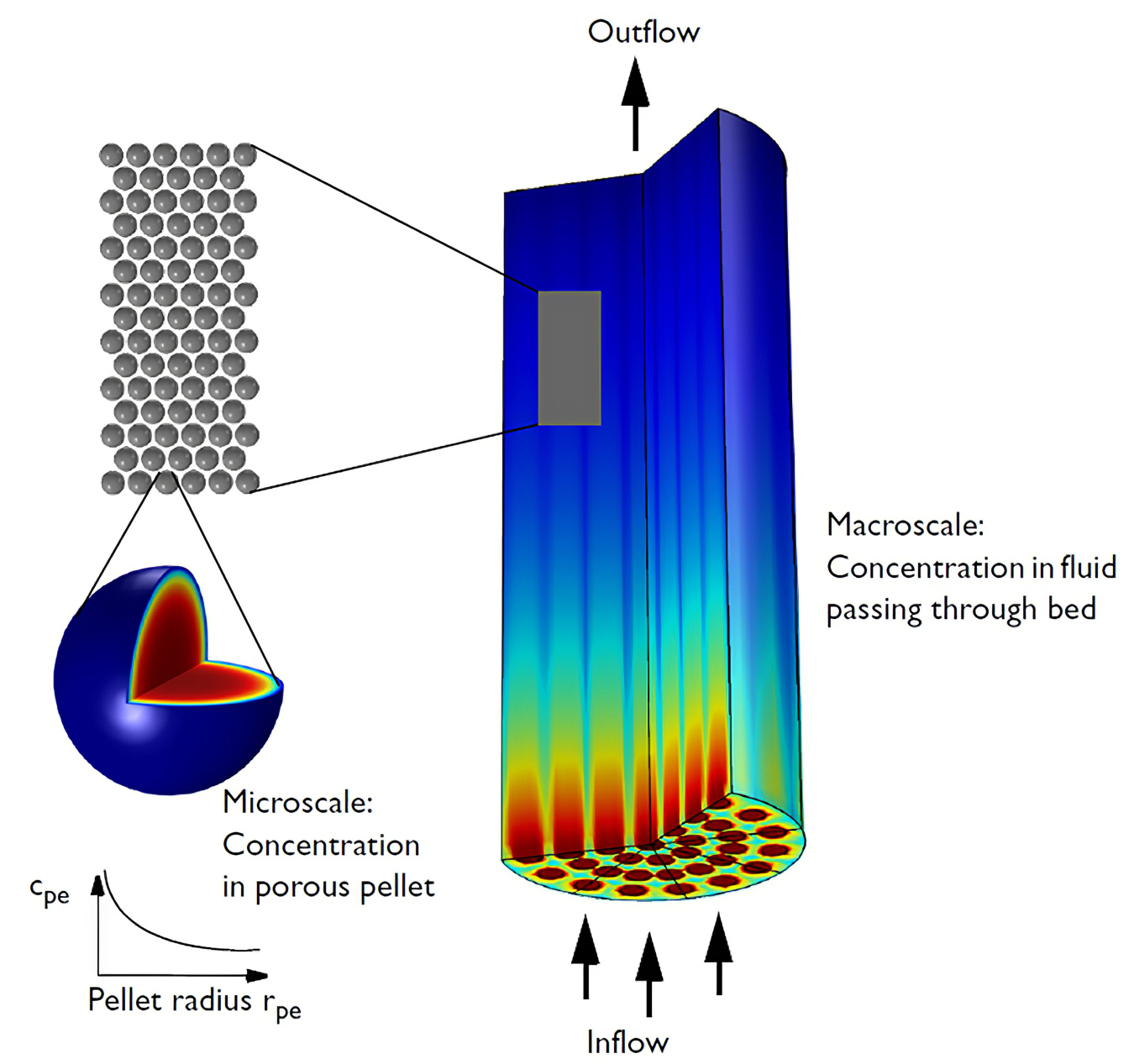
Figure 1. The multi-scale packed bed model. Image made using COMSOL Multiphysics® software and is provided courtesy of COMSOL.
The finite element model of the catalytic upgrading reactor was constructed with the COMSOL Multiphysics® software package.
As shown in Figure 1, the reactor is composed of many porous, spherical catalyst particles packed into the reactor. Catalyst size, porosity, and packing density impact pressure drop and limits for process gas flow rate. In this case, the diameter of each catalyst is 0.5 mm. The model simulations of the reactor also included a configuration with three internal air-blown cooling tubes to supplement the limited flow of process gas.
Results from simulations of oxidative decarbonization of the catalyst upgrading reactor are shown in Figure 2. The model shows sharp temperature gradients occurring from the wave of oxygen flowing through the reactor as the carbon oxidizes and heat is transferred to the catalyst particles. The model indicated a high probability of physical catalyst damage and deactivation due to:
- Excessive temperatures
- Temperature gradients
- Heating and cooling rates
The utility of the model is apparent in the results, as the model predicted the viability of the conceptual pilot-scale process in place of a costly reactor construction and operation effort that would take much more time than the model-based study. Ongoing research is investigating alternative reactor designs that may minimize the temperature gradients in the fixed-bed model.
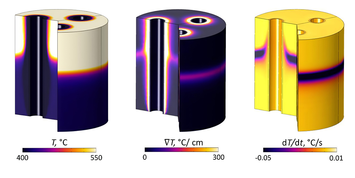
Figure 2: Model results quantifying thermal excursions when a fixed-bed reactor of a coked catalyst with three air-blown cooling tubes is oxidatively decarbonized. The images show high temperatures (left), sharp temperature gradients (middle), and high heating or cooling rates (right) at t = 3 hours. Image courtesy of Bruce Adkins, Oak Ridge National Laboratory.
[1] Bruce D. Adkins, Zach Mills, James Parks II, M. Brennan Pecha, Peter N. Ciesielski, Kristiina Iisa, Calvin Mukarakate, David Robichaud, Kristin Smith, Katherine Gaston, Michael Griffin, and Josh Schaidle, “Predicting Thermal Excursions During In Situ Oxidative Regeneration of Packed Bed Catalytic Fast Pyrolysis Catalyst,” React. Chem. Eng, 2021, 6, 88. https://doi.org/10.1039/D1RE00007A.