
The Power of Wind
Wind turbines harness the wind—a free and widely available renewable energy source—to generate electric power. This page offers a text version of the interactive animation: Explore a Wind Turbine.
How a Wind Turbine Works
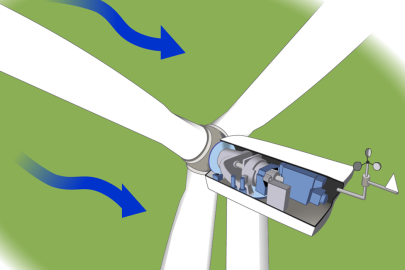
A wind turbine turns wind energy into electricity using the aerodynamic force from the rotor blades, which work like an airplane wing or helicopter rotor blade. When wind flows across the blade, the air pressure on one side of the blade decreases. The difference in air pressure across the two sides of the blade creates both lift and drag. The force of the lift is stronger than the drag and this causes the rotor to spin. The rotor connects to the generator, either directly (if it's a direct drive turbine) or through a shaft and a series of gears (a gearbox) that speed up the rotation and allow for a physically smaller generator. This translation of aerodynamic force to rotation of a generator creates electricity.
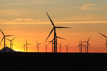
How a Wind Plant Works
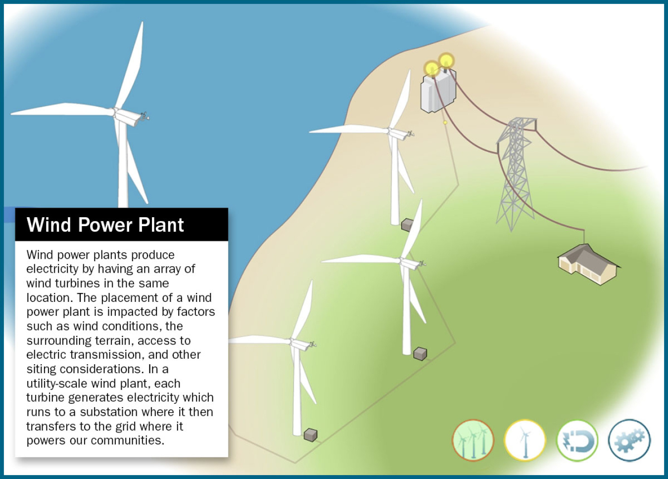
Wind power plants produce electricity by having an array of wind turbines in the same location. The placement of a wind power plant is impacted by factors such as wind conditions, the surrounding terrain, access to electric transmission, and other siting considerations. In a utility-scale wind plant, each turbine generates electricity which runs to a substation where it then transfers to the grid where it powers our communities.
Transmission
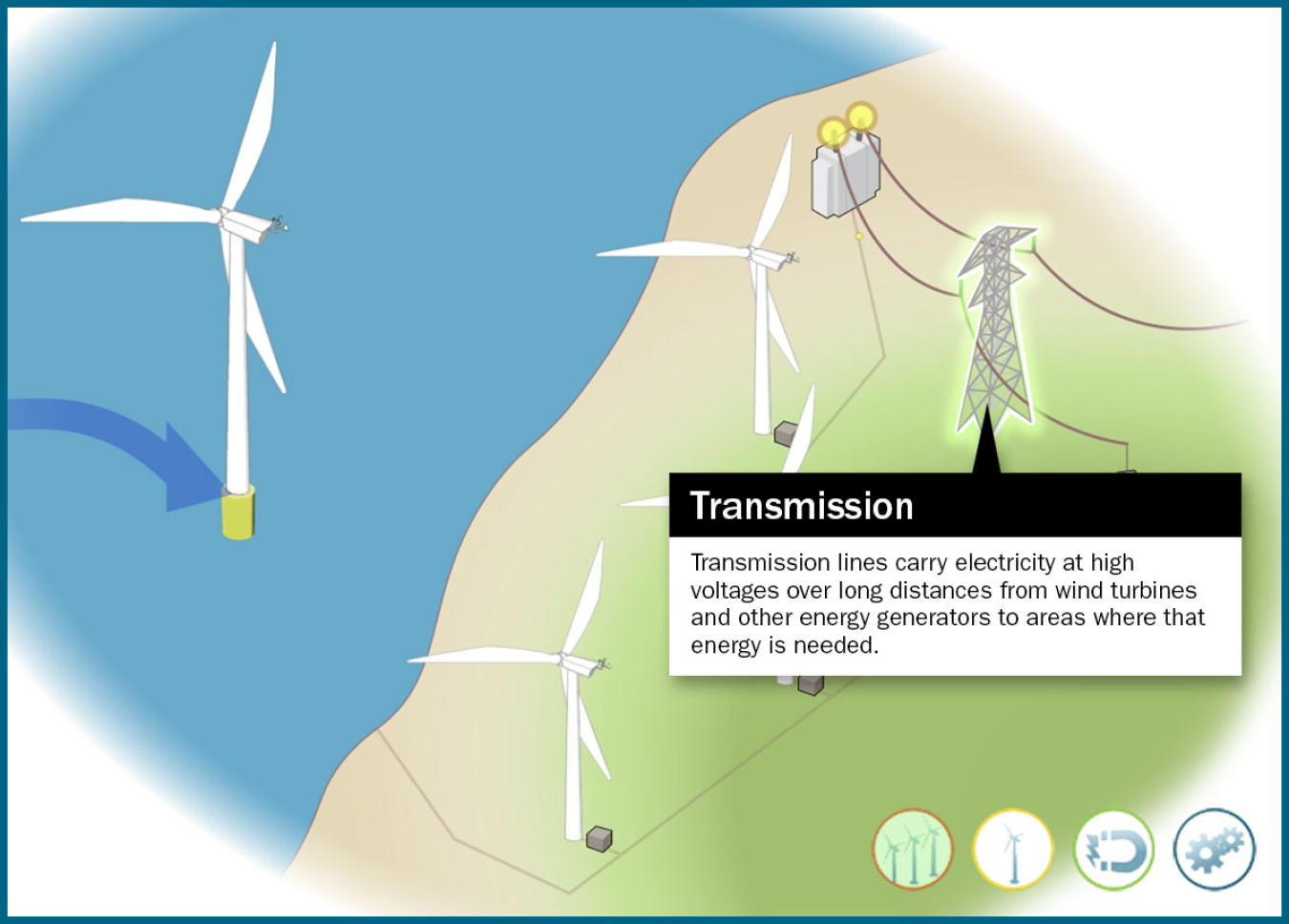
Transmission lines carry electricity at high voltages over long distances from wind turbines and other energy generators to areas where that energy is needed.
Transformers
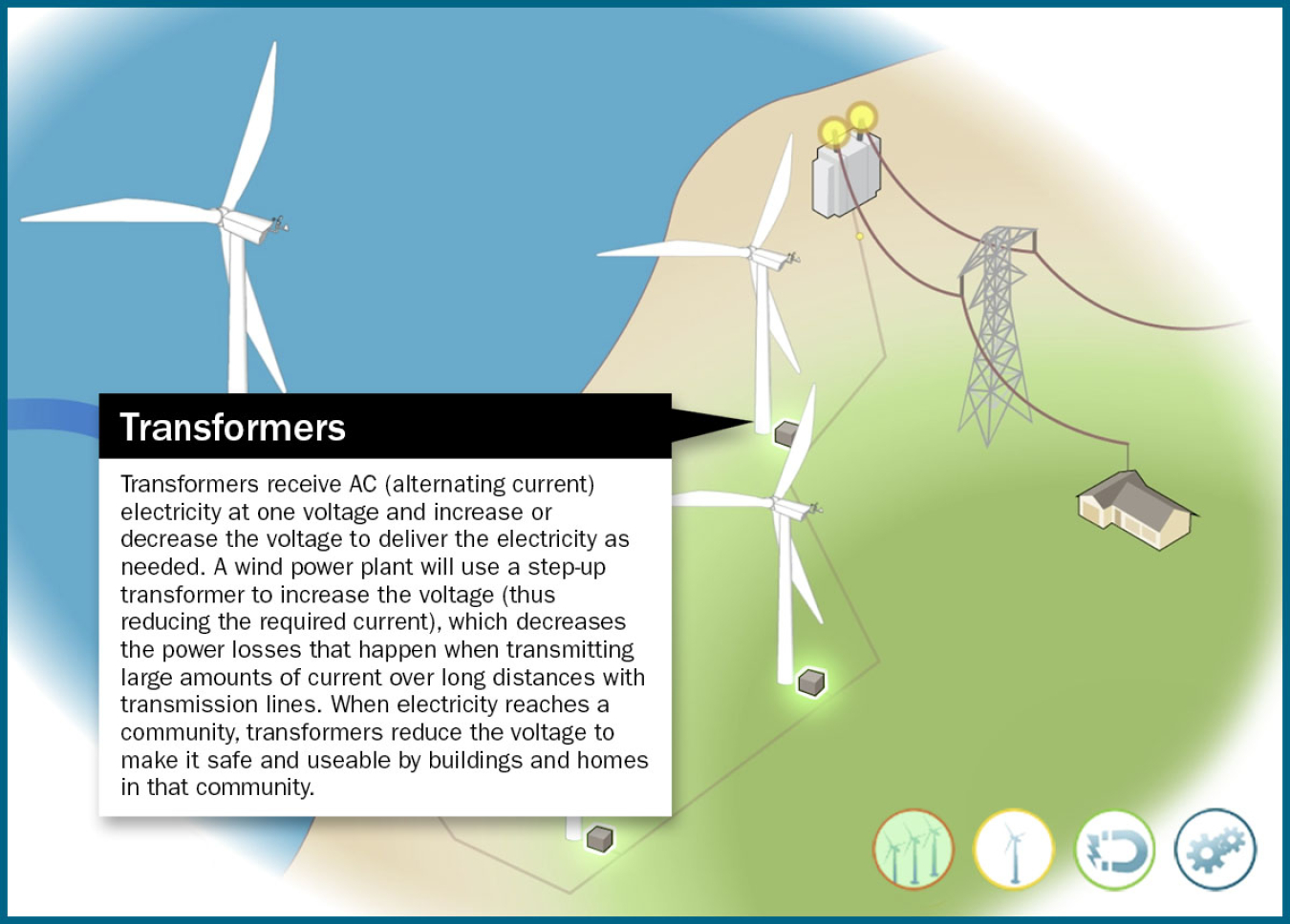
Transformers receive AC (alternating current) electricity at one voltage and increase or decrease the voltage to deliver the electricity as needed. A wind power plant will use a step-up transformer to increase the voltage (thus reducing the required current), which decreases the power losses that happen when transmitting large amounts of current over long distances with transmission lines. When electricity reaches a community, transformers reduce the voltage to make it safe and useable by buildings and homes in that community.
Substation
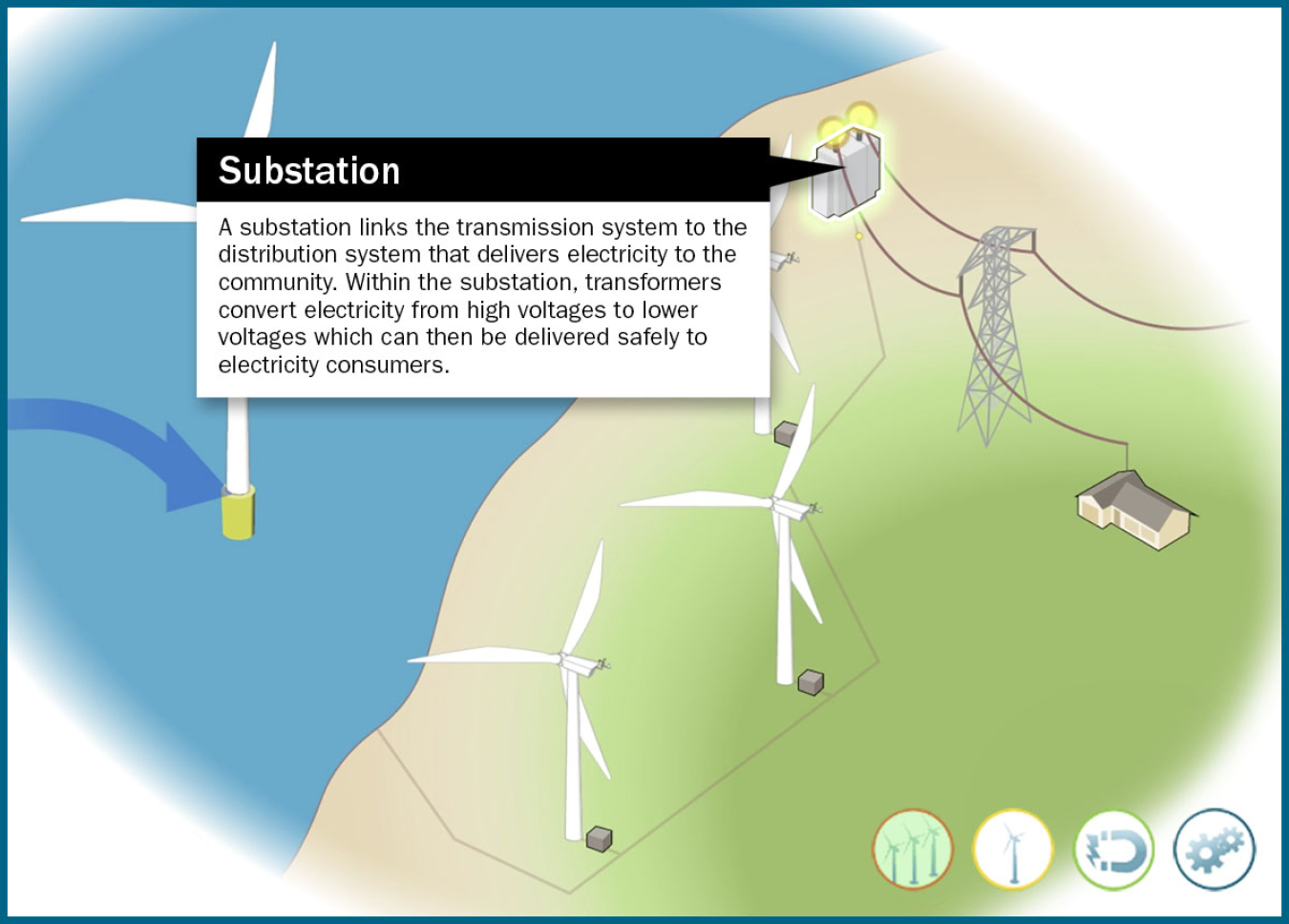
A substation links the transmission system to the distribution system that delivers electricity to the community. Within the substation, transformers convert electricity from high voltages to lower voltages which can then be delivered safely to electricity consumers.
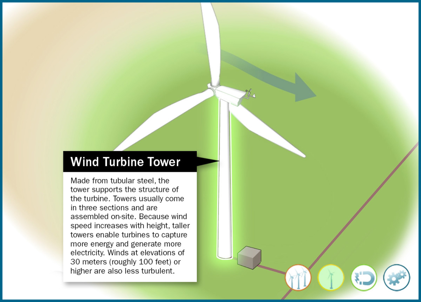
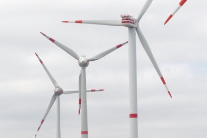
Wind Turbine Tower
Made from tubular steel, the tower supports the structure of the turbine. Towers usually come in three sections and are assembled on-site. Because wind speed increases with height, taller towers enable turbines to capture more energy and generate more electricity. Winds at elevations of 30 meters (roughly 100 feet) or higher are also less turbulent.
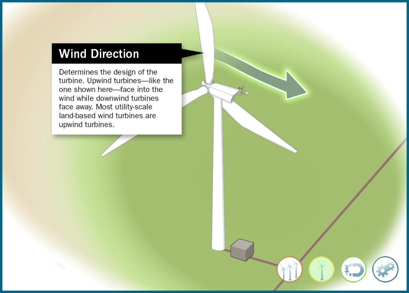
Wind Direction
Determines the design of the turbine. Upwind turbines—like the one shown here—face into the wind while downwind turbines face away. Most utility-scale land-based wind turbines are upwind turbines.
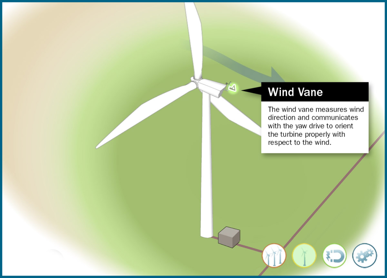
Wind Vane
The wind vane measures wind direction and communicates with the yaw drive to orient the turbine properly with respect to the wind.
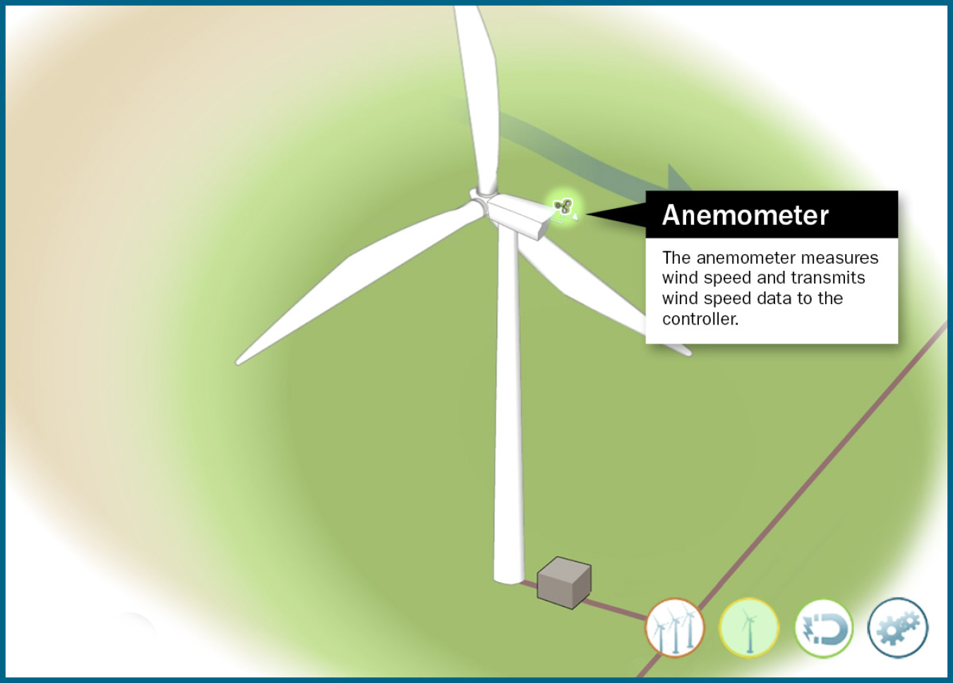
Anemometer
The anemometer measures wind speed and transmits wind speed data to the controller.
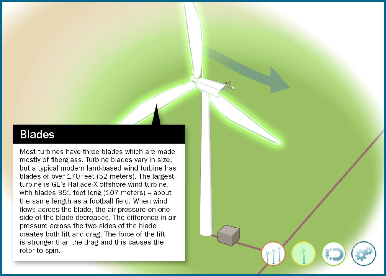
Blades
Most turbines have three blades which are made mostly of fiberglass. Turbine blades vary in size, but a typical modern land-based wind turbine has blades of over 170 feet (52 meters). The largest turbine is GE's Haliade-X offshore wind turbine, with blades 351 feet long (107 meters) – about the same length as a football field. When wind flows across the blade, the air pressure on one side of the blade decreases. The difference in air pressure across the two sides of the blade creates both lift and drag. The force of the lift is stronger than the drag and this causes the rotor to spin.
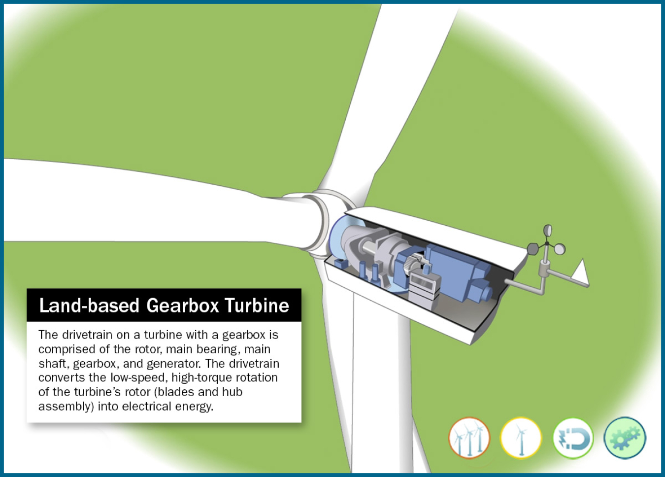
Land-Based Gearbox Turbine
The drivetrain on a turbine with a gearbox is comprised of the rotor, main bearing, main shaft, gearbox, and generator. The drivetrain converts the low-speed, high-torque rotation of the turbine’s rotor (blades and hub assembly) into electrical energy.
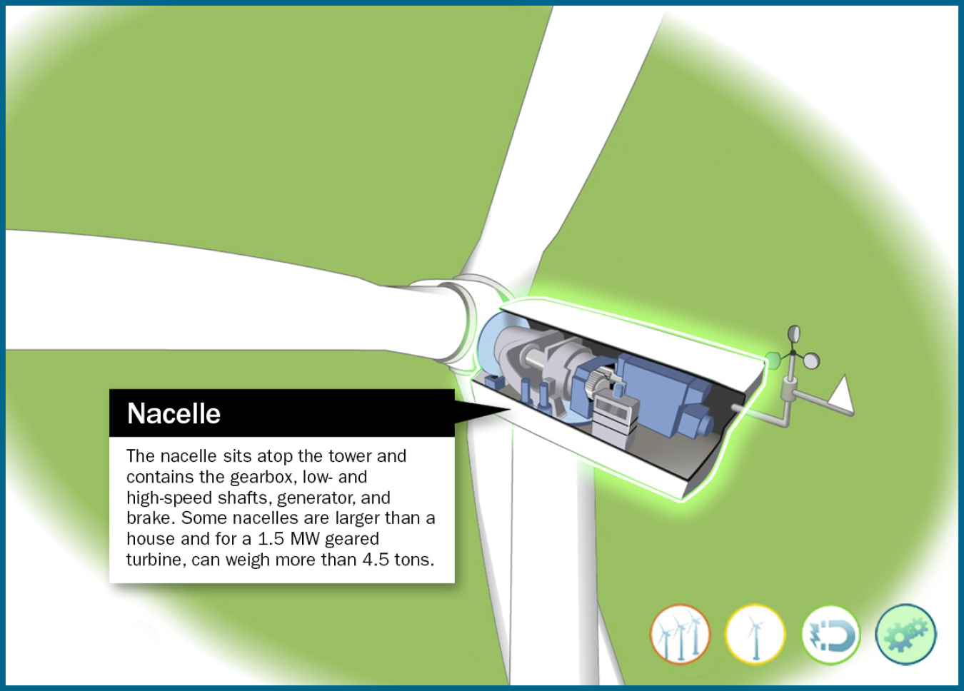
Nacelle
The nacelle sits atop the tower and contains the gearbox, low- and high-speed shafts, generator, and brake. Some nacelles are larger than a house and for a 1.5 MW geared turbine, can weigh more than 4.5 tons.
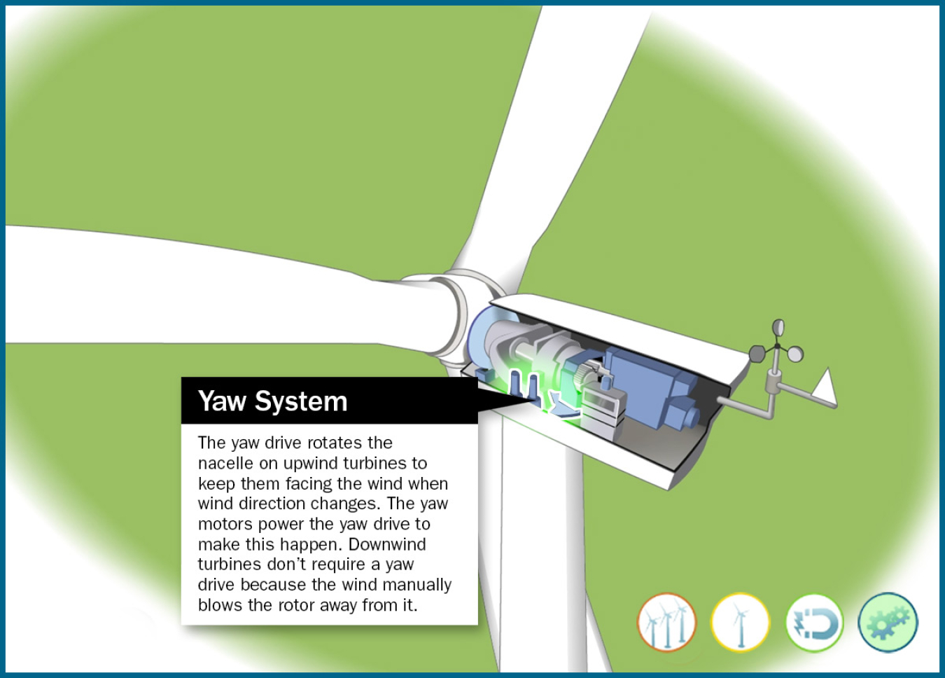
Yaw System
The yaw drive rotates the nacelle on upwind turbines to keep them facing the wind when wind direction changes. The yaw motors power the yaw drive to make this happen.
Downwind turbines don’t require a yaw drive because the wind manually blows the rotor away from it.
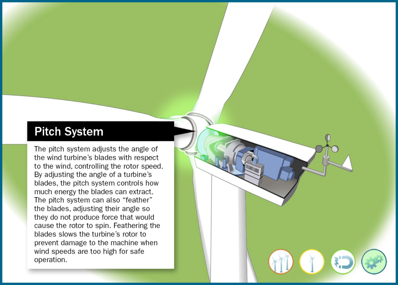
Pitch System
The pitch system adjusts the angle of the wind turbine's blades with respect to the wind, controlling the rotor speed. By adjusting the angle of a turbine's blades, the pitch system controls how much energy the blades can extract. The pitch system can also "feather" the blades, adjusting their angle so they do not produce force that would cause the rotor to spin. Feathering the blades slows the turbine's rotor to prevent damage to the machine when wind speeds are too high for safe operation.
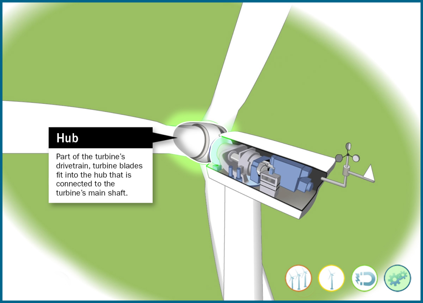
Hub
Part of the turbine's drivetrain, turbine blades fit into the hub that is connected to the turbine's main shaft.
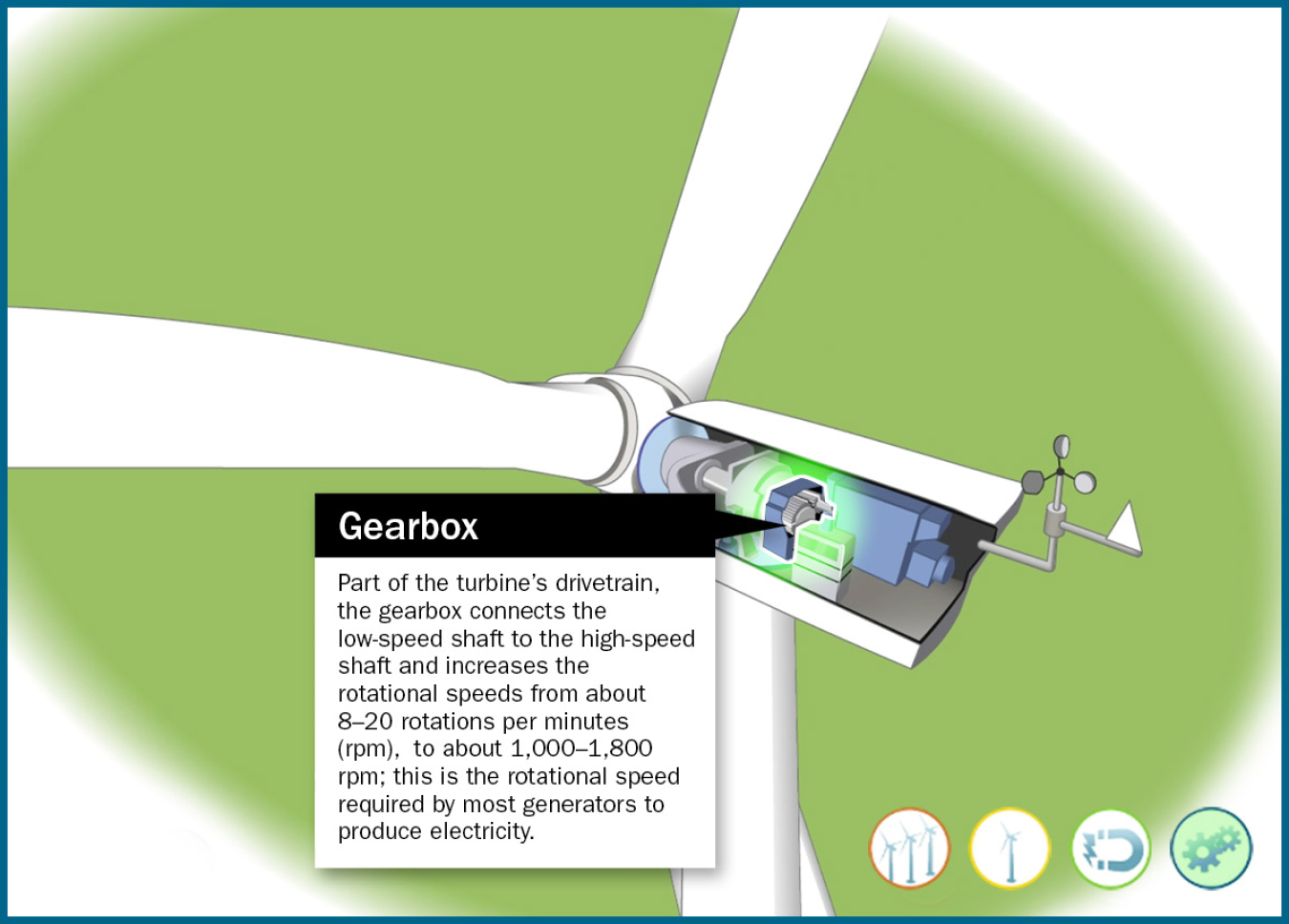
Gearbox
The drivetrain is comprised of the rotor, main bearing, main shaft, gearbox, and generator. The drivetrain converts the low-speed, high-torque rotation of the turbine's rotor (blades and hub assembly) into electrical energy.
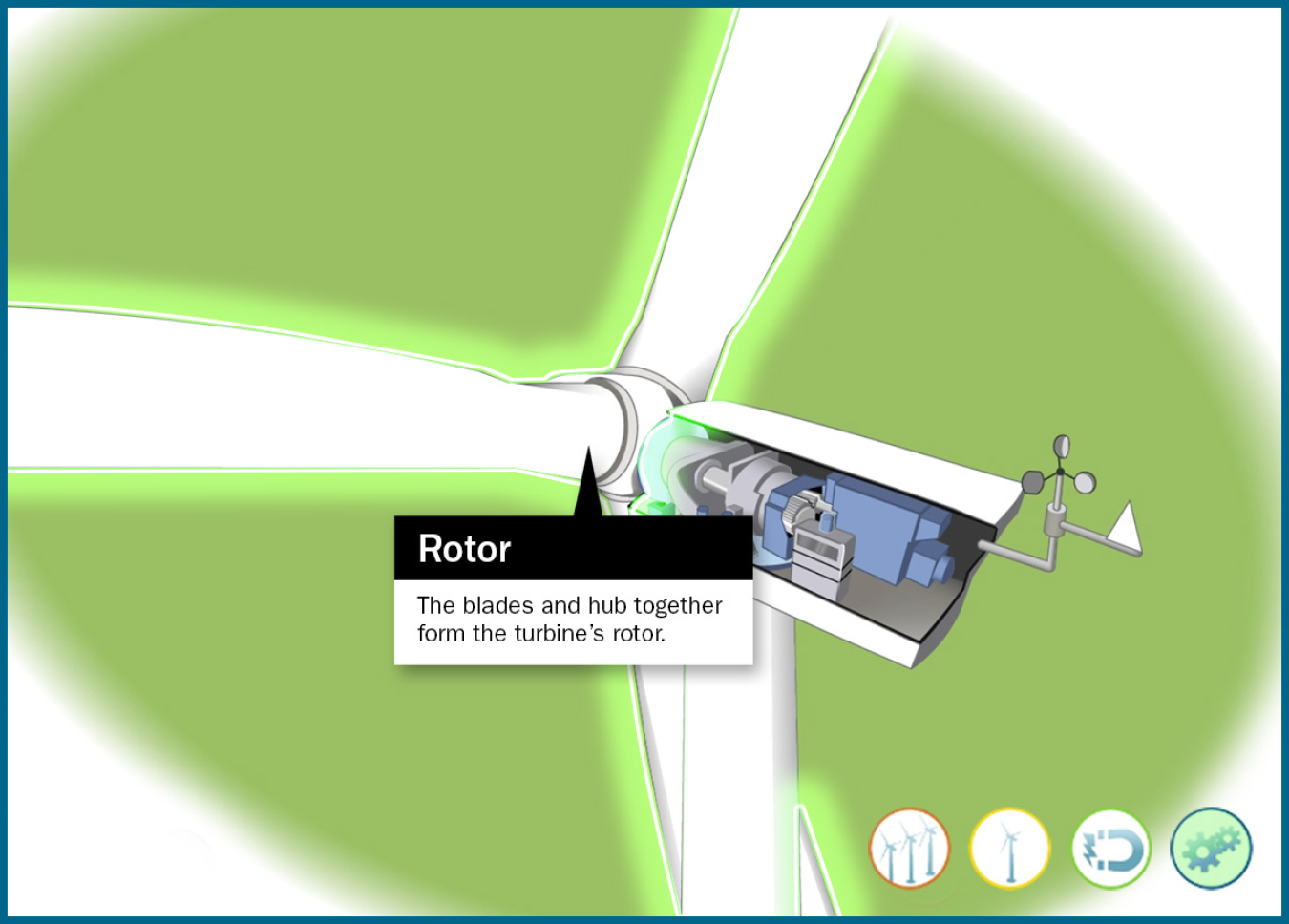
Rotor
The blades and hub together form the turbine's rotor.
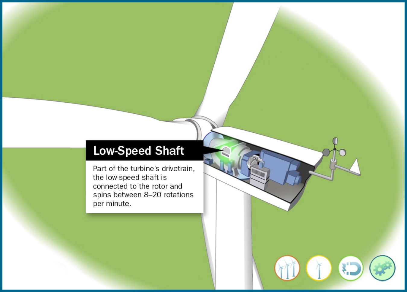
Low-Speed Shaft
Part of the turbine's drivetrain, the low-speed shaft is connected to the rotor and spins between 8–20 rotations per minute.
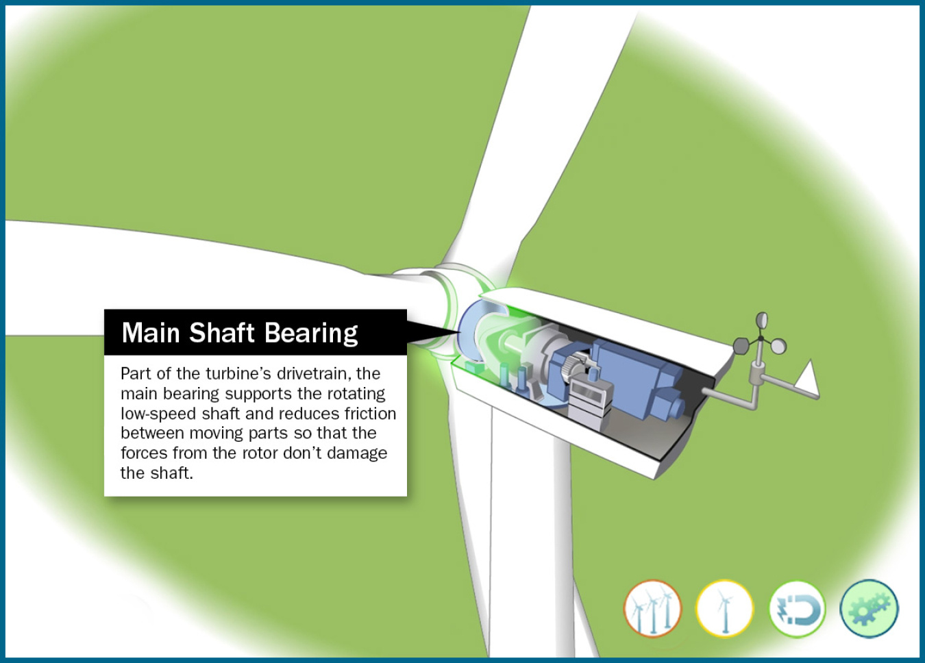
Main Shaft Bearing
Part of the turbine's drivetrain, the main bearing supports the rotating low-speed shaft and reduces friction between moving parts so that the forces from the rotor don't damage the shaft.
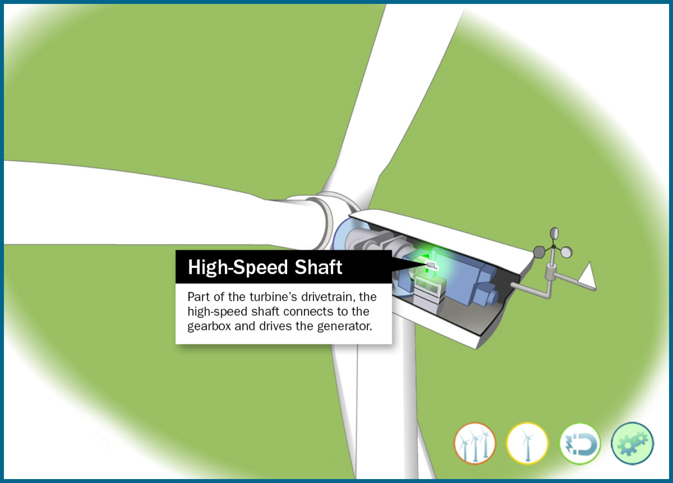
High-Speed Shaft
Part of the turbine's drivetrain, the high-speed shaft connects to the gearbox and drives the generator.
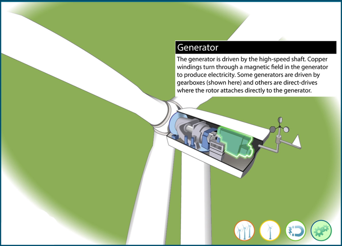
Generator
The generator is driven by the high-speed shaft. Copper windings turn through a magnetic field in the generator to produce electricity. Some generators are driven by gearboxes (shown here) and others are direct-drives where the rotor attaches directly to the generator.
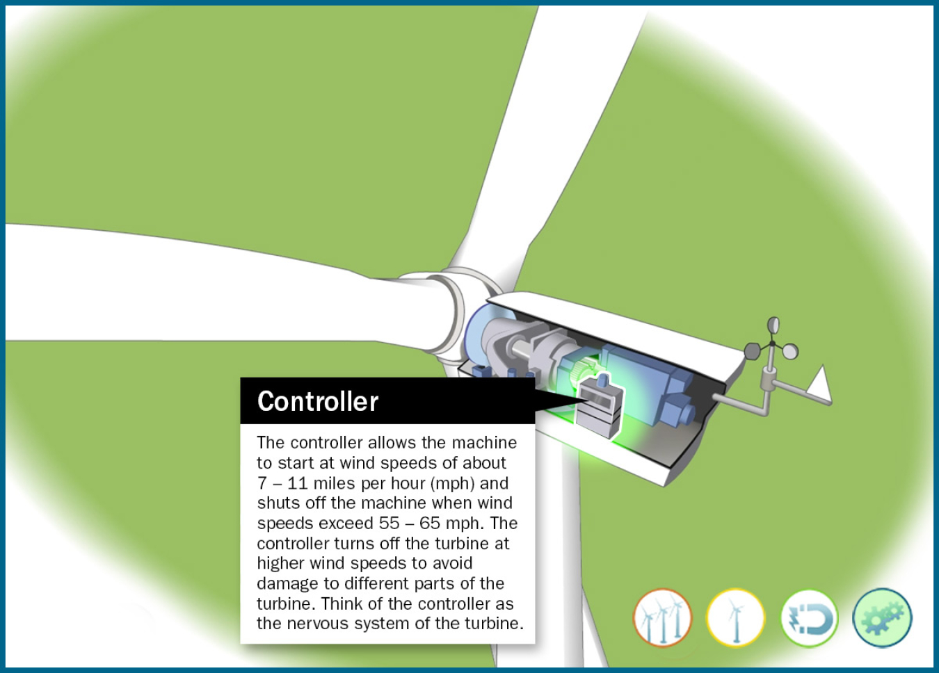
Controller
The controller allows the machine to start at wind speeds of about 7–11 miles per hour (mph) and shuts off the machine when wind speeds exceed 55–65 mph. The controller turns off the turbine at higher wind speeds to avoid damage to different parts of the turbine. Think of the controller as the nervous system of the turbine.
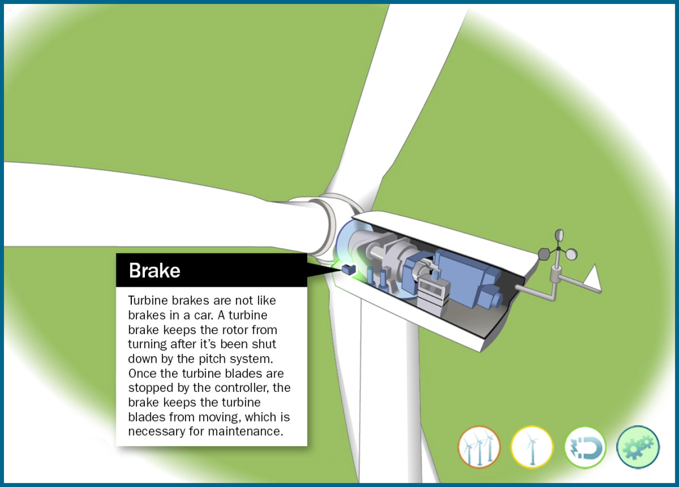
Brake
Turbine brakes are not like brakes in a car. A turbine brake keeps the rotor from turning after it's been shut down by the pitch system. Once the turbine blades are stopped by the controller, the brake keeps the turbine blades from moving, which is necessary for maintenance.
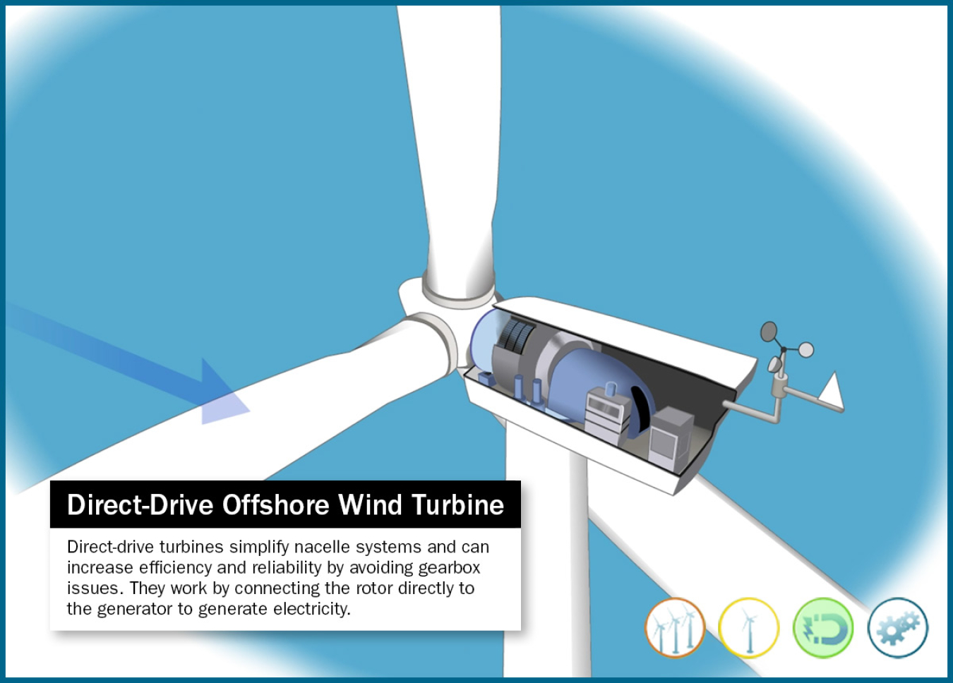
Direct-Drive Offshore Wind Turbine
Direct-drive turbines simplify nacelle systems and can increase efficiency and reliability by avoiding gearbox issues. They work by connecting the rotor directly to the generator to generate electricity.
Direct-Drive Offshore Wind Vane and Anemometer
The wind vane measures wind direction and communicates with the yaw drive to orient the turbine properly with respect to the wind.
The anemometer measures wind speed and transmits wind speed data to the controller.

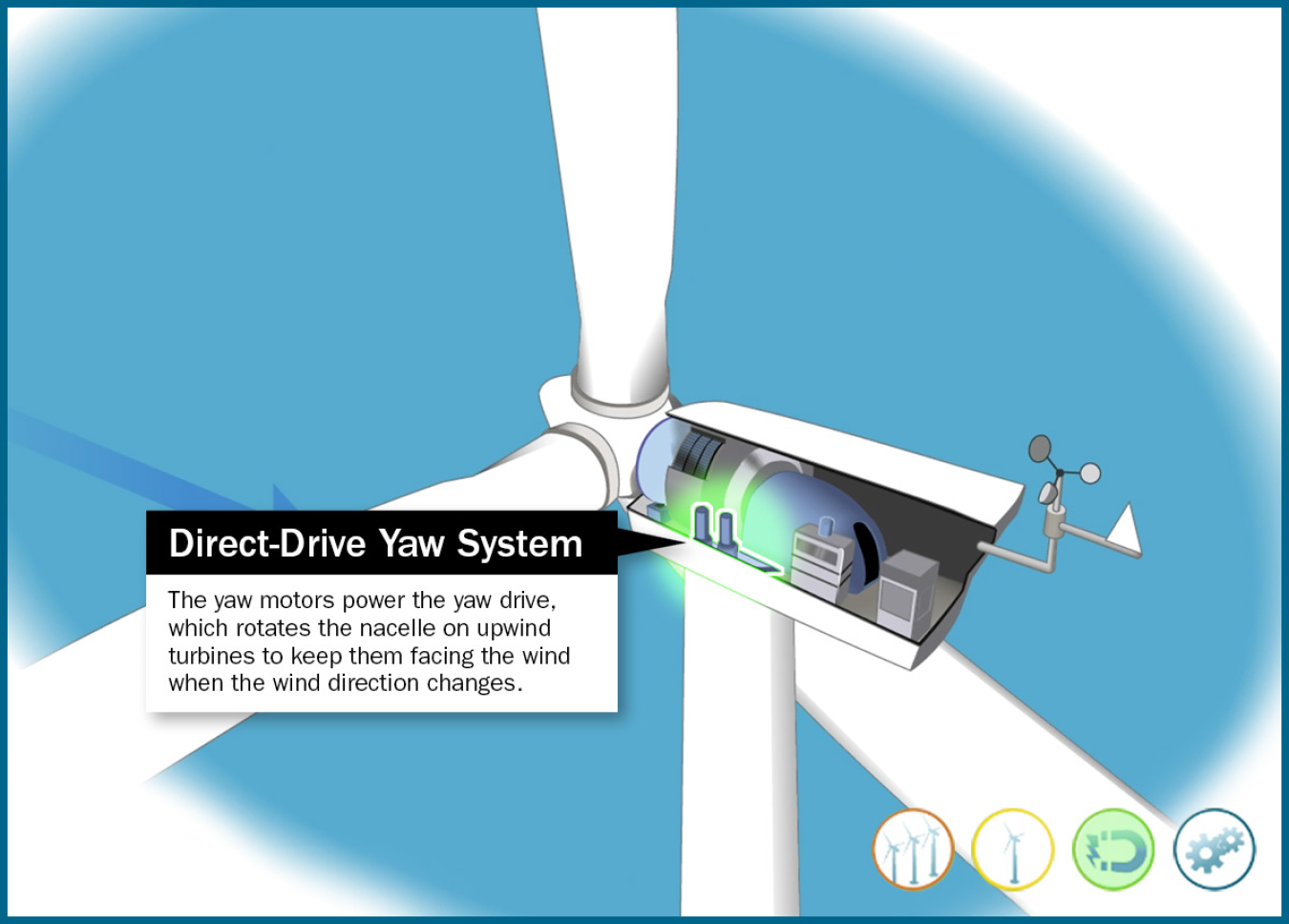
Direct-Drive Yaw System
The yaw motors power the yaw drive, which rotates the nacelle on upwind turbines to keep them facing the wind when the wind direction changes.
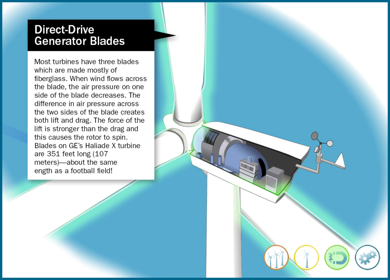
Direct-Drive Generator Blades
Most turbines have three blades which are made mostly of fiberglass. When wind flows across the blade, the air pressure on one side of the blade decreases. The difference in air pressure across the two sides of the blade creates both lift and drag. The force of the lift is stronger than the drag and this causes the rotor to spin. Blades on GE's Haliade X turbine are 351 feet long (107 meters) – about the same length as a football field!
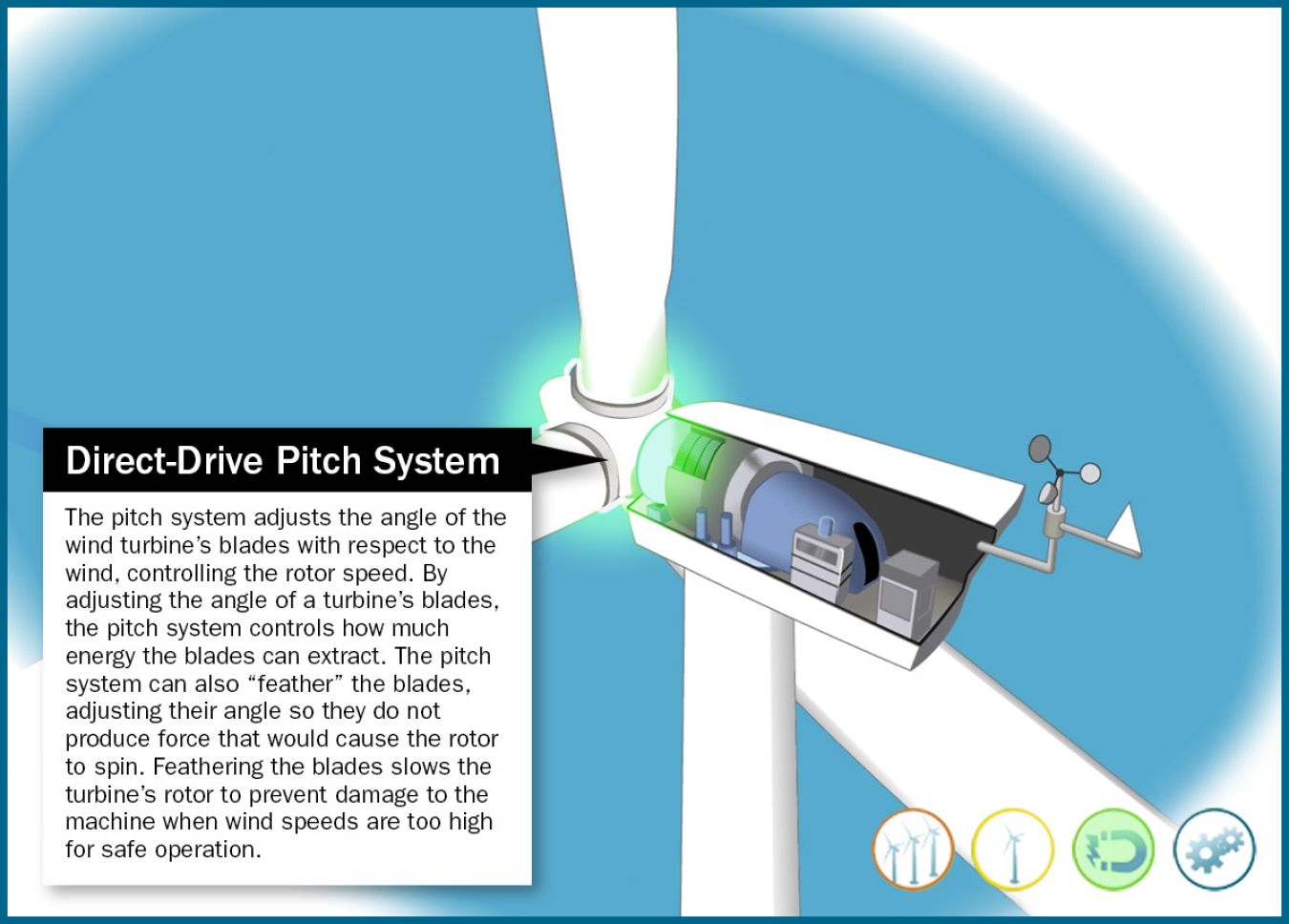
Direct-Drive Pitch System
The pitch system adjusts the angle of the wind turbine's blades with respect to the wind, controlling the rotor speed. By adjusting the angle of a turbine's blades, the pitch system controls how much energy the blades can extract. The pitch system can also "feather" the blades, adjusting their angle so they do not produce force that would cause the rotor to spin. Feathering the blades slows the turbine’s rotor to prevent damage to the machine when wind speeds are too high for safe operation.
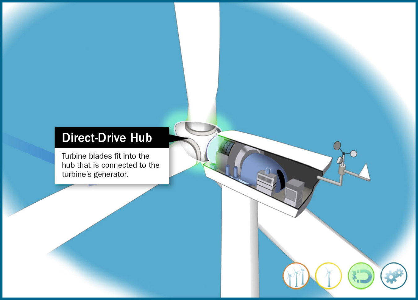
Direct-Drive Hub
Turbine blades fit into the hub that is connected to the turbine's generator.
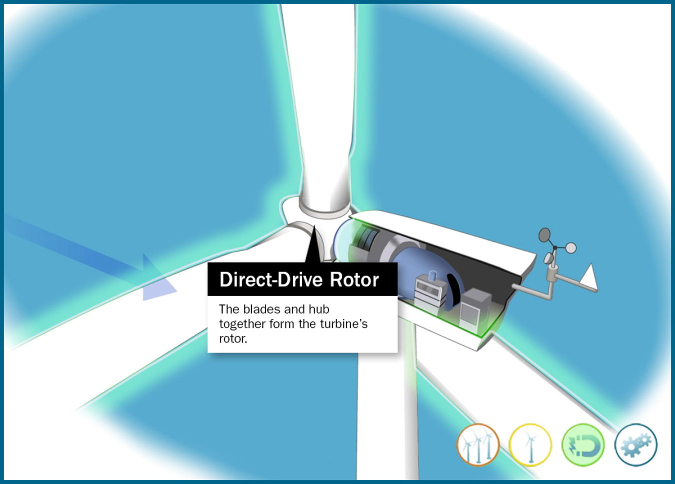
Direct-Drive Rotor
The blades and hub together form the turbine's rotor.
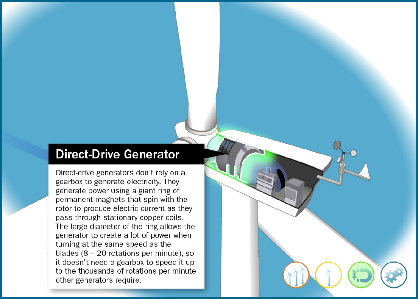
Direct-Drive Generator
Direct-drive generators don't rely on a gearbox to generate electricity. They generate power using a giant ring of permanent magnets that spin with the rotor to produce electric current as they pass through stationary copper coils. The large diameter of the ring allows the generator to create a lot of power when turning at the same speed as the blades (8–20 rotations per minute), so it doesn't need a gearbox to speed it up to the thousands of rotations per minute other generators require.
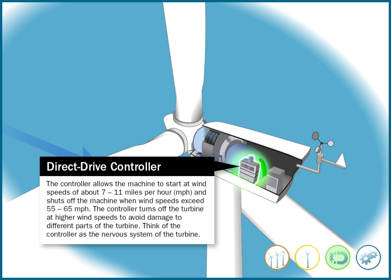
Direct-Drive Controller
The controller allows the machine to start at wind speeds of about 7–11 miles per hour (mph) and shuts off the machine when wind speeds exceed 55–65 mph. The controller turns off the turbine at higher wind speeds to avoid damage to different parts of the turbine. Think of the controller as the nervous system of the turbine.
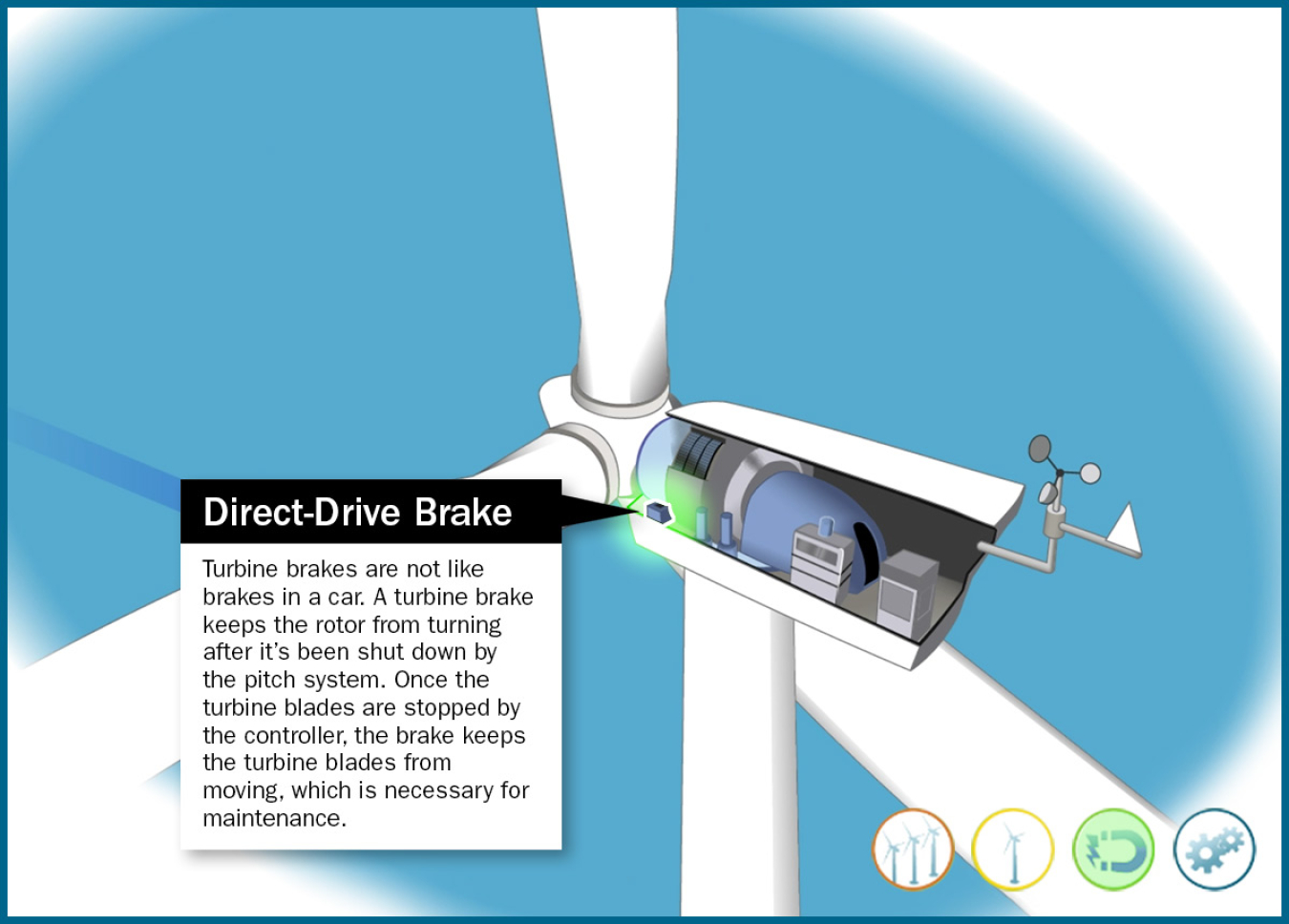
Direct-Drive Brake
Turbine brakes are not like brakes in a car. A turbine brake keeps the rotor from turning after it's been shut down by the pitch system. Once the turbine blades are stopped by the controller, the brake keeps the turbine blades from moving, which is necessary for maintenance.
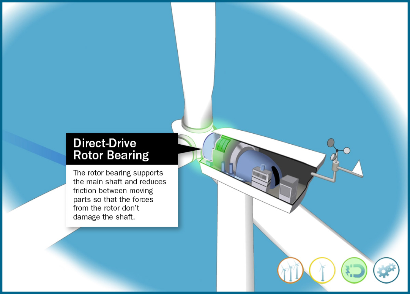
Direct-Drive Rotor Bearing
The rotor bearing supports the main shaft and reduces friction between moving parts so that the forces from the rotor don't damage the shaft.
Learn More
-
 Learn more about wind, from how a wind turbine works to research in the field of wind energy.
Sign up to receive the latest news, updates, and opportunities from the Integrated Energy Systems Office.